Blowing up airships in FreeCAD and Python
And ironing out the little wrinkles along the way

Designing tensile structures from fabric, and inflated structures in particular, is a tricky problem that generally requires specialized and proprietary software. A designer may have a desired 3-dimensional shape in mind, but the manufacturing will be based on 2D fabric patterns cut and seamed together. Achieving the 2D designs that result in the desired 3D shape requires significant iteration. It’s also important to approximate the stretching and wrinkling of fabric, especially for doubly-curved surfaces, and taking into account the anisotropic behaviour of a woven material.1
When possible I like to have control, visibility, and ownership of my workflow, so naturally I went about seeing if I could do this in FreeCAD.2 FreeCAD doesn’t have tensile-structure design capability built in, but it does provide a powerful Python interface, which basically means there’s no feature it doesn’t have. Where there’s a will, there’s a way.

The first question is one of big-picture strategy. There are two possible approaches: the first would be to have the software automatically unwrap a designer’s 3D model into the necessary 2D planar patterns; the second would be to go the other way, starting from a designer’s 2D patterns and virtually stitching them together and inflating and tensioning the fabric to produce the resulting 3D shape. The way the software works will structure the rest of the design process. This is the classic “top-down” vs “bottom-up” dichotomy.

The idea of starting with 3D has a lot of appeal, because it lets the computer automate more of the heavy lifting, leaving less work on the designer’s plate. But I decided that starting from 2D would be a better approach for several reasons which I’ll explain in the footnotes. Before reading them, you might enjoy considering the problem yourself for a few minutes to decide which method you would choose, and why.3
The process starts with sketching some 2D pattern cut-outs, known as gores. These are drawn parametrically in FreeCAD’s Sketcher workbench. FreeCAD is able to convert the sketch into a scalable vector graphic (SVG) file, which is easy to work with in Python.

Here I’m sketching a design where eight gores will be seamed together to create a hull shape with four integrated fins. Holes will be left in each fin to create space for manoeuvring thrusters, just for the fun of seeing what that would look like.
I then write JSON files defining the properties of each gore: its material characteristics, the orientation of the fabric, the groups of edges that define it, and how those edges will be connected to the edges of other gores. (A GUI could certainly make this process more user-friendly, but for a quick project, it’s easy enough to just write the JSON by hand). Additional JSON files also define properties like envelope pressure.
The next step is to perform a constrained Delaunay triangulation on each gore. I used Triangle to do the triangulation itself,4 and this fantastic article by Ian Henry was a great help for understanding and efficiently manipulating the data structures involved. I’ve aligned the triangles to a grid that matches the weave of the material as closely as possible, to minimize the inaccuracy of the simulation.

I’ve used a simple nonlinear fabric model which essentially assumes an infinitely-thin elastic membrane. This membrane can stretch and support tensile and shear forces, but it has zero stiffness in bending or compression.5 To support anisotropic materials, the stiffness of each tensile element is allowed to depend on its orientation with respect to the weave axis.
Because the model is nonlinear (tension and compression forces resolve differently), the raw Delaunay triangle mesh alone is not sufficient: it would have an inconsistency in how it resolves shear forces, which would depend on the orientation of the triangles.
To correct this, I add additional edges joining the vertices across each triangle edge. These edges act as membrane elements, but do not have any faces associated with them. Fortunately, Triangle’s well-organized output makes this process easy to automate. The resulting structural mesh looks like this:

Next, each of the gores are given an initial orientation in 3D space. This doesn’t need to be precise; it just needs to be good enough that the balloon doesn’t end up inside-out or something. To find a good-enough solution automatically, the gores are kept rigid while the adjacent boundary vertices are connected together with virtual springs. Since there are eight gores connected symmetrically, the solution is an octagon.

Next, those edges are “seamed” together, merging vertices and edges along the gore boundaries and thereby creating a single mesh in 3D space:

Finally the fun part! I simulate pressure on the triangle faces, and tension forces throughout the mesh according to the local strain on the fabric. I was expecting to have to write this part in C++ for performance, but it actually vectorizes extremely well using Numpy, resulting in quick-enough simulation straight from Python even for decently high-resolution meshes. Each iteration consists of:
Computing the “stretches” of each edge, relative to its initial unstretched length. The result is an array of edge deformation values.
When positive (ie, the fabric is in tension), these are multiplied by the edge’s stiffness to get a tension force. This force is applied to each vertex in the direction of that edge.
Computing the area vector of each triangle face from the cross product of two edges. The magnitude of the area vector represents the area, and its direction is perpendicular to the triangle face.
The pressure force is the product of the pressure difference across that triangle, times the triangle's area vector. The pressure force is distributed evenly among each triangle’s vertices.6
Finally, the vertices are each displaced in proportion to their net applied force, and then the process is repeated.7

Once the simulation has converged, the resulting 3D model is exported to the OBJ format, which can be read back into FreeCAD’s modelling workspace to add motors, hard points, and so on.

Well, that was fun! With this tool in hand, let’s answer two mysteries that have perplexed humankind since 1923: Why do inflated structures wrinkle along the seams, and why does the Goode homolosine projection look like… clown pants?

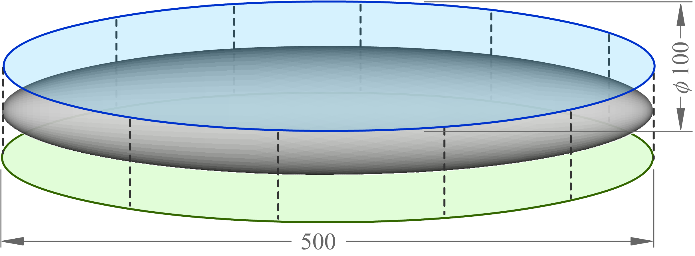
There’s a good reason. Let’s say I want to make a basic ellipsoid-of-revolution shape, like this:

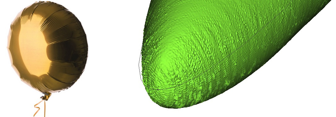
And let’s say I want to manufacture it really cheaply, like a dollar-store mylar balloon, from just two gores heat-seamed together. As a first try, perhaps the easiest thing would be to just trace the shadow of our ellipsoid and use that as our pattern.
It’s tempting to imagine that if we sew together 2D patterns that each look like the desired 3D shape, the end result will be close enough. Unfortunately we will be disappointed. For one, our hypothetical balloon is a lot smaller and narrower than we wanted:
“Ah,” you say. “Of course it’s too small. Imagine drawing lines of longitude and latitude around our ellipsoid. We need to at least make sure that our material is wide enough to match the total circumference of each of those lines.” Good point! Around the midsection, for example, our patterns only allotted a total of 200 mm of material, but the minor circumference of the 3D design should have been 100π, so we’re 141 mm short. No wonder it ended up being slim! This observation suggests a new method, where we follow these lines of longitude as we unwrap the surface, and ensure they all end up the appropriate length on the 2D pattern, as much as possible:

However, because the material is planar and our ellipsoid is not, we cannot preserve circumferences for the green, blue, and orange lines all at the same time. We have to break at least one of them. In the 3D volume, the orange circumference should be exactly twice as long as the green, but in the flattened shape it ends up considerably longer than that. So in this case, there is too much material along the orange perimeter, relative to how much material exists along the green and blue lines.
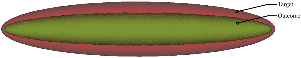
When we inflate this shape we do get a very good match; I’ve overlaid them here and it’s quite hard to tell the two shapes apart:

But because of the excess material along the seam circumference, the seams are wrinkled. Like a mylar balloon. For two separate reasons (which I'll explain in the footnotes) those wrinkles become more severe in the areas near the nose, where the curvature is the sharpest.8
If only there were some way to take some of that excess material out from the perimeter…. Oh yeah, there is! But I admit, it's stretching the limits of my diagramming abilities. Basically, we can intersect the ellipsoid with a corrugated sheet, creating a zig-zag cut that chops that orange line into pieces. Each of these cuts creates an opportunity to remove excess local material near the seam.
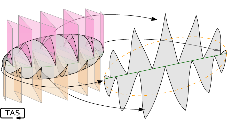
This reduces the local distortion at each point in the fabric, which reduces wrinkling. (It admittedly gets quite hard to sew, though.) And the possibilities don’t stop there — we could cut the surface with a helix! — but that’s as far as I’ll take this article.

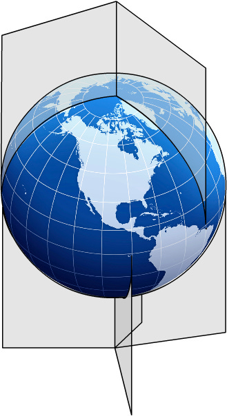
The Goode homolosine projection is an attempt to flatten the globe in a way that minimizes local distortions of the surface area, so that Greenland doesn’t end up bigger than Africa.9 While Goode wasn't specifically aiming to avoid wrinkles when pasting the map onto a spherical globe or sewing it into a beach ball, it turns out those properties come along together.
If you find this project interesting, do let me know!

This post isn’t intended as professional engineering advice. If you are looking for professional engineering advice, please contact me with your requirements.
Anisotropy refers to any situation where material properties are different along different axes. By contrast, isotropy is the situation where material properties are the same in every direction. For example, a sheet of rubber is isotropic because it has no preferred orientation; it doesn’t contain fibres aligned in any particular way. Woven materials and composites tend to be strongly anisotropic, unless many layers are overlaid and pressed together.
The field of textiles has a lot of terminology for talking about fabric anisotropy, such as warp, weft, grain, selvedge, and bias. I’m sure that some readers who do textile crafts, either as a hobby or professionally, will be familiar with these terms, but many readers will not, so I will try to use less specialized language, where possible, to keep the article accessible.
FreeCAD has a steep learning curve that has earned it some detractors, but I love it. The mainstream release was already good enough, but I’d like to give a special shoutout to Link Branch, developed by the incredible Zheng “realthunder” Lei, for taking FreeCAD to the next level. In my view, FreeCAD has reached about 90% of the functionality of proprietary CAD (Computer Aided Design) packages like SolidWorks, and comes with so many other advantages — like its ability to act as a geometry API for other programs. Plus it’s free, which makes it a great fit for things like STEM summer programs for kids.
There’s no question that commercial packages are more user-friendly, and a lot of people are overwhelmed by FreeCAD on the first encounter. I highly recommend following JokoEngineering’s tutorials on Youtube, even if you’re the kind of person who prefers to dive in and mess around without reading the instruction manual. Oh, and start with the “Part Design” workbench.
Every project involves big decisions like these, right up near the very top level. These are the critical decisions that can either save lots of time if you get them right early on, or cause big schedule overruns if you get them wrong. I can’t make a general ruling in favour of top-down or bottom-up design; they each have merits and the right approach will depend on the circumstance. But here are the signposts that pulled me toward bottom-up in this case:
There is no unique solution to the unwrapping of a 3-dimensional surface, so a single 3D model may correspond to an infinite number of 2D patterns. On the other hand, a 2D pattern with seaming instructions does specify a unique final shape. This isn’t a rule, but a 1-to-1 mapping is a strong signal of this being “the right way”.
Among these infinite solutions to unwrapping a 3D surface, not all are equally good: some unwrappings will be much better than others in terms of manufacturability, symmetry, seam length, efficiency of material use, and strength. The designer would need some way to formally communicate their preferences to the software to constrain its search for a solution, and writing that specification alone would probably take more work than simply doing the design work themselves.
The stretch and wrinkling of the fabric depends on the details of the 2D pattern, meaning that going from 3D to 2D would require a very difficult iterative inverse-solving procedure. By contrast, going from 2D to 3D requires only a straightforward physics simulation.
Going from 2D to 3D aligns with the manufacturing process and the structural physics, so it implicitly ensures that the final design will be realizable. If the designer were directly specifying the 3D geometry, it is easy for them to accidentally create practically-unmanufacturable shapes, or ones that would be unsupportable for a tensile membrane structure.
Going from 2D to 3D takes some iteration to get the 3D shape just right, but it’s not hard. In practice it only takes a little experimenting with 2D patterns and seeing the resulting 3D shapes for the designer to get a strong intuitive sense of how to design these structures well. (If you’re having trouble, you can find a potato that resembles the shape you want, carefully peel it, and study the shape of the potato peel). And if you want to get fancy, the inflated 3D geometry can be compared against a reference to generate an error-map that can be used to automatically refine an initial cut pattern.
Unfortunately, the licensing terms for Triangle are somewhat… absent. I really like Triangle because it’s fast and works extremely well, its interface is simple, and it has all the features I need, like the ability to define internal nodes and holes. The output is also well organized, with nicely-ordered edges and so on. But if I were going to share this project or build a FreeCAD plugin, I would probably switch to another library with more transparent licensing, like CDT.
Under bending or compression forces, a thin fabric will fold and buckle. A real fabric can still support some force without buckling, or even after buckling, but much much less than it can under tension. I decided that rounding these to zero would be accurate enough for my purposes.
Actually, you can’t apply pressure right away, because the initial just-stitched state is so badly deformed along the boundaries that the seam-bordering triangles have unrealistically huge area. This can result in really badly-behaved pressure forces which distort the boundary-adjacent triangles even more, literally blowing up the solution. It’s best to run the calculation with just the material-strain forces until the maximum edge deformation has settled down a bit, and then introduce the pressure forces.
This footnote is for the people who asked: “Wait, aren’t you simulating physics here? According to Newton’s law, shouldn’t the net force be proportional to an acceleration? Why are you using it as a displacement?”
Good question! The answer is that I’m not attempting a dynamic simulation here, but rather a static one. The calculation is done via repetitive iterations, but those are not “timesteps”; there is no time dimension involved. (A dynamic simulation, with actual timesteps, would be needed if I wanted to generate, say, a realistic animation of the process of inflating the envelope, but that’s not what I’m trying to find.) The static solution will be where the vertex positions are such that all the forces nicely balance. Any method that quickly and reliably converges on this result is acceptable, from an accuracy perspective. Using momentum-like terms — where displacements have additional corrections applied which depend on the errors in previous iterations — can help accelerate this convergence, but this is a careful balance against solver stability. There are a lot of other optimizations that could speed up the simulation too, such as propagating tension forces across non-nearest-neighbouring edges. If this program were going to be run many times, it would be worth fine-tuning the solver, but the tradeoff is between time spent running the software vs. time spent writing it. Ultimately, if it converges to the right shape, that’s good enough for me.
One of these reasons is that, as we can see from the curvature of the blue lines in the diagram, this is where the unwrapping is the most non-Euclidean, where the local surface area of fabric in the flattened pattern differs most severely from the surface area of the desired 3D shape. The other reason is that the fabric tensile stress is also lowest in this area, where the radius of curvature is small:

(This is an approximate formula for tensile stress in a doubly-curved thin-walled container, where P is the pressure, t is the wall thickness, and r₁ and r₂ are the radii of curvature along two axes. It assumes the tensile stress is equal in both directions, which is not guaranteed, but it’s good enough for this discussion.)
That tensile stress helps to stretch the slightly-elastic fabric out, which (somewhat) helps to impart true compound curvature onto the flat material.
Goode doesn’t quite succeed; there are still large skew distortions in East Asia, even if the areas remain close to uniform. Those could be relieved by adding another cut, but presumably he didn’t want to break up the landmass.
By the way, rather than a corrugated sheet, the cuts in the Goode homolosine projection look more like this: